Homebrew Antenna used for Satellite and HF communication.
This page edited the article on a Japanese page by JE2TLZ. Contents
14-28MHz 0.41-0.6λ Vertical antenna
5/8λ Vertical antennas perform well but are too long.
Longer elements perform better.
Calculated by MMANA
| wavelength | 0.25 | 0.53 | 0.59 | 0.6 | 0.625 |
|---|---|---|---|---|---|
| Gain dBi | 0 | 1.98 | 3.23 | 3.47 | 4.13 |
PG ANT 100 fiberglass rod is Length on a 9.7m was 21MHz 0.6λ.
The shortening ratio of the covered wire was 0.96.
ANT circuit
SWR&Z 14-18MHz_Vert_250514.png ,Vert21-28MHz_059_swr.gif ,Vert28MHz-059_swr.gif
Vert25MHz-8m.gif ,Vert28MHz-7m.gif
SWR range is narrow as it is LC-matched.
ANT photo , Matching Box photo
Matching Box photo2 ,Matching Box photo3 ,Matching Box photo4
HF Full-sized whip antenna for cars
Vertical antenna for car. ANT photo
14MHz_SWR&Z 14MHz_WhipANT1.png
It's better to install an antenna in the center of the car.
Change by a location on the car. carvert21-.gif
It could be used by a connection directly, but an adjustment Transformer was made.
Unun32-50 photo、Circuit unun1625cir2.PNG, SWR&Z unun16-25kc2.png
A Transformer is put on the RIG side.
| Element cm | f0 MHz | Z Ω |
|---|---|---|
| 504 | 13.9 | 31.5 |
| 406-30 | 18.1 | 35.1 |
| 406-80 | 21.0 | 49.8 |
"-" in the element is tip wrap.
Rectangular loop ANT (21to28MHz)
Good antenna in a vertical surface.
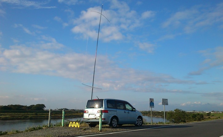
Width 2.34m , height 5.12m , full length 14.25m of an element.
I produced the reduction effect of covering wire.
Adjusted by 21MHz is 1:1 balun. 24&28MHz by LC adjustment circuit. It's changed by the switch.
Impedance matching circuit LoopANTmach.PNG、Matching Box photo
The Large LC adjustment circuit was done small.
28MHz of SWR less than 2 was 700KHz.
HF Top Loading Verttical Dipole
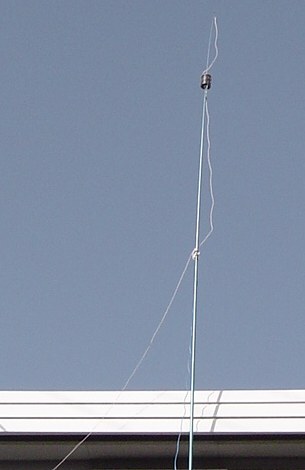
- The material
- Fishing rod of fiberglass (5.4m or 6.3m)
- Electric wire (1.25m2*2)
- Aluminum line (2 or 2.5mm in diameter)
- Plastic Pen stand, Plastic board (diameter 94mm,lengt 100mm)
- 1:1Balun
Upper Element by 0.9m above from the coil at the time of 1.6m last from the coil.
The length of the Loading Coil is 106mm, and 96mm in the diameter.
Photograph of Hi-Q Loading Coil
| Band | Loading Coil | Lower side element |
|---|---|---|
| 14MHz | 14Turn | 4.535m |
| 18MHz | 8T(short 6T) | 3.69m |
| 21MHz | 5T(short 9T) | 3.20m |
| 24.9MHz | 3T(short 11T) | 2.70m |
| 28MHz | no(short ALL) | 2.20m |
The frequency is switched by manual control.
The coil is short-circuited because of bottom toward the center.
I measured Verttical DP the miniVNA → VerticalDP14-21.png,VerticalDP25.png
50MHz Hentena Antenna
| Length | Width | Feed point |
|---|---|---|
| 300cm | 99cm | 67cm from the bottom |
The pole is made of aluminium pipes 16mm and 14mm,
divided into 5 sections and inserted, for a total length of 5m.
The horizontal element is 1m of aluminium pipe 12mm,
fixed with a large clip, with a terminal at the end.
The vertical element is 1.5mm copper wire;
the 1:1 balun is a ferrite toroidal core.
SWR&Z hentena50MHz.png, SWR 2.0 and below was 1MHz.
The width is said to be closer to 50Ω if it is slightly narrower than 1/6λ.
Loop Antenna
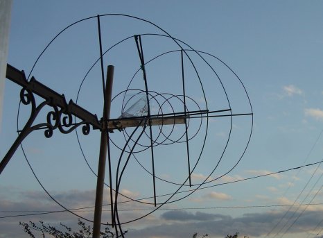
146MHz 3ele Loop ANT Gain 10.0dbi SWR2> 3.4MHz(MMANA)
| Element | Spacing | Loop Diameter | Circumference | Diameter |
|---|---|---|---|---|
| Re | 390mm | 681.2mm | 2140mm | 3.0mm |
| Ra | -- | 651.6 | 2047 | 3.0 |
| De | 450 | 627.7 | 1972 | 3.0 |
I measured 145MHz3eleLoop the miniVNA → 3ele_loop_2m2.png
435MHz 4ele Loop ANT Gain 11.9dbi SWR2> 8.7MHz(MMANA)
| Element | Spacing | Loop Diameter | Circumference | Diameter |
|---|---|---|---|---|
| Re | 148mm | 232mm | 730mm | 3.0mm |
| Ra | -- | 218.0 | 685 | 3.0 |
| D1 | 193.5 | 214 | 672 | 3.0 |
| D2 | 195 | 211 | 664 | 3.0 |
This 4eleLoop changed to wide a little more 3eleLoop because vertical pattern was too narrow.
435MHz 3ele Loop ANT Gain 10.2dbi SWR2>10.6MHz(MMANA)
| Element | Spacing | Loop Diameter | Circumference | Diameter |
|---|---|---|---|---|
| Re | 127mm | 232mm | 728mm | 3.0mm |
| Ra | -- | 218 | 685 | 3.0 |
| D1 | 173 | 210 | 661 | 3.0 |
432MHz 5ele Loop ANT _ EME could be received.
| Element | Spacing | Loop Diameter | Circumference | Diameter |
|---|---|---|---|---|
| Re | 174mm | 233mm | 732mm | 3.0mm |
| Ra | -- | 221 | 694 | 3.0 |
| D1 | 196 | 213 | 669 | 3.0 |
| D2 | 246 | 211 | 664 | 3.0 |
| D3 | 242 | 210 | 661 | 3.0 |
The material is wood, a plastic stick, an aluminum line, and a pressure terminal.
All Loop ANT is Impedance matchings are only 1:1 Balun.(Bazooka Match)BazookaMatch.png
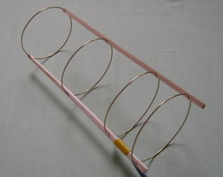
1269MHz 4ele Loop ANT Gain 11.7dbi (MMANA)
| Element | Spacing | Loop Diameter | Circumference | Diameter |
|---|---|---|---|---|
| Re | 41mm | 79.2mm | 248.9mm | 1.2mm |
| Ra | --- | 77.6 | 234.8 | 1.2 |
| D1 | 69 | 72.2 | 226.7 | 1.2 |
| D2 | 76 | 70.3 | 221 | 1.2 |
The Satellite QSO me with a portable transceiver with this small antenna.
(AO-51 L/U mode, Only 1W QRP!) Rig00640s.jpg
Yagi-Uda Antenna
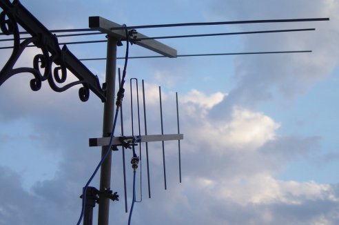
145MHz 3ele Yagi-Uda ANT Gain 9.0dbi SWR2> 2.3MHz(MMANA) 270g
| Element | Spacing | Length | Height | Diameter |
|---|---|---|---|---|
| Re | 248.1mm | 1010mm | 6.0mm | |
| Ra | -hafeFD- | 940.5 | 23mm | 5.0 |
| Di | 558.2 | 895.5 | 5.0 |
I measured 145MHz3eleYagi the miniVNA → 3eleYagi_2m.png
435MHz 5ele Yagi-Uda ANT Gain 11.3dbi SWR2> 13.3MHz(MMANA) 220g
| Element | Spacing | Length | Height | Diameter |
|---|---|---|---|---|
| Re | 100mm | 343.9mm | 5.0mm | |
| Ra | -FD- | 304.5 | 16.5mm | 4.0 |
| D1 | 132.3 | 314 | 5.0 | |
| D2 | 196.4 | 297 | 5.0 | |
| D3 | 228.8 | 283 | 5.0 | |
| old_Ra | -FD- | 304.5 | 17.5mm | 3.0 |
The material is wood, an aluminum pipe(5&6mm), and a brass pipe(3&4mm).
5ele Yagi ANT is Impedance matchings are only 1:1 Balun.
2427MHz 7ele Yagi-Uda ANT
| Element | Spacing | Length | Height | Diameter |
|---|---|---|---|---|
| Re | 12.6mm | 61.6mm | 5.0mm | |
| Ra | -FD- | 52.0 | 10.0mm | 2.0 |
| D1 | 11.7 | 53.3 | 5.0 | |
| D2 | 17.0 | 52.4 | 5.0 | |
| D3 | 26.0 | 51.4 | 5.0 | |
| D4 | 31.1 | 50.0 | 5.0 | |
| D5 | 35.0 | 48.0 | 5.0 |
Point of Design
Reproducibility improves when designing in wideband.
Impedance falls though it becomes wideband when the element is made fat, and Gain rises, too.
To raise Gain, the interval of Di is widened more than Re.
The antenna simulation is confirmed.
The difference of the resonance frequency according to the shape of the loop was examined.
| Loop model | Side | Loop length | Area | percentage | MMANA-f0 | NEC2-f0 | difference | percentage |
|---|---|---|---|---|---|---|---|---|
| Triangle | 0.667m | 2.0m | 0.157m2 | 49.4% | 165.77MHz | 165.15MHz | -0.62MHz | 103.8% |
| Quadrangle | 0.500 | 2.0 | 0.250 | 78.6% | 163.96 | 163.21 | -0.75 | 102.6% |
| Octagon | 0.250 | 2.0 | 0.302 | 95.0% | 160.96 | 160.12 | -0.84 | 100.7% |
| 16polygon | 0.125 | 2.0 | 0.314 | 98.7% | 160.52 | 159.06 | -1.46 | 100% |
| Circle | 0.318 | 2.0 | 0.318 | 100% | ? | ? | ? | ? |
The difference between the simulation and the measurement was examined.
| Antenna | MMANA(miniNEC) | NEC-2 for MMANA | difference | Measured value | difference |
|---|---|---|---|---|---|
| 146MHz3eleYagi | 146.1MHz | 145.8MHz | -0.3MHz | 146MHz | Close value |
| 435MHz5eleYagi | 436.5 | 432.5 | -4.0 | 432 | Close value |
| 146MHz3eleLoop | 147.5(octagon) | 147.2(octagon) | -0.3 | 146 | It is lower |
| 146MHz3eleLoop | 146.14(16polygon) | 146.12(16polygon) | -0.02 | 146 | Close value |
| 435MHz4eleLoop | 437.5(octagon) | 437.1(octagon) | -0.4 | 433.5 | It is lower |
| 435MHz4eleLoop | 433.98(16polygon) | 433.81(16polygon) | -0.17 | 433.5 | Close value |
NEC-2 calculates the ground effect.
MMANA Data file of all antennas
These Antennas were designed by using MMANA & NEC2 for MMANA.Thank you for wonderful software.

最終更新時間:2025/11/17 14:12:24